

Downloadable PDF version of the DuctMaster III User Manual
Additional information included in PDF version:
• Parts and Accessories List
• Optional Parts and Accessories List
• Specifications
• Glossary
UNPACKING INSTRUCTIONS
Remove the outer box and inspect for damage. Report all damage immediately to your carrier. If special set-up instructions are required, they will be taped to the outside of the equipment or in the “Operating” section of this manual.
Inspect all the packing material for small parts before discarding packaging material. Report all damage to Air-Care immediately. Any attempt at repairing suspected damages may void warranty.

A) Air-Care DuctMaster III w 1.5” Hose 1 ½” X 35’ Brush and Motor Assembly. Includes 12” Pancake-Style Brush
B) 4th Stage HEPA, 13-3/8” x 17-5/8 x 3-1/8”
C) 3rd Stage 13” x 15” x 1” Electra Silver Washable filter
D) Universal Remote
Dryer Vent Cleaning Kit
E) Drill Powered Dryer Duct Cable (5/16’ core x20 ft) with 4” Brush
F) Adapter – 3 inch I.D. Hose to 2 Inch Tools
G) Nest Claw
H) 3” x 4” x 3” “Y” Adapter
I) Lint Brush, 24”
J ) Dryer Exhaust Flap Clip
DuctMaster/Vent Vac Accessory Kit
K) Equipment Bag
L) Dual Stage 15 Gal. Bag Filter (5/pkg.)
M) Hose, 3” x 8.3’ W/Cuffs
N) Wand .1.25” OD (2)
O) Crevice Tool 1.25”
P) Upholstery Tool 1.25”
Q) Floor Tool 1.25”
R) Upholstery Brush 1.25”
S) Wand 1.25” OD (1)
T) Adapter, 3” to 2” Hose Cuff (Fits the 1-1/2 and 2” Cuffs on Red or Blue Hose, and Grey vacuum hose with tools.
SAFETY PRECAUTIONS
Always think safety and use common sense precautions when working with Air-Care equipment. Do not block walkways with equipment and remove delicate and breakable articles from the immediate work area. The following are precautions that should be reviewed by all persons who will be involved in the cleaning activity.
• Other than the 3 filters, the brush and the Batteries in the Remote, there are no user serviceable components in Air-Care DuctMaster or Vent Vac. Only trained technicians should attempt to make internal repairs on this equipment.
• ALWAYS unplug both power cords before removing the covers to change filters or clean the internal parts of the DuctMaster.
• Inspect AC power plugs to be sure the ground pins are in place.
• NEVER connect power to Air-Care equipment unless all covers and safety shields are in place. Mechanical and electrical parts could activate without warning and cause injury.
• NEVER allow anyone but a properly trained technician to use the equipment.
• All Air-Care equipment is designed for US standard 115-volt, 60 Hz AC. The Air-Care DuctMaster is optionally available in 220/240 Volt, 50/60 Hz Power. ALWAYS check the specifications on the equipment before connecting electrical power to Air-Care Equipment.
SET-UP AND TESTING
The Air-Care DuctMaster has significantly MORE static pressure than Air-Care TurboJet Negative Air Machines and will be able to pull heavy, moist (But NOT WET) or sandy construction debris out of dryer vents, commercial ducts, chimneys, and restoration areas. It is NOT meant to be a wet vacuum for liquids.

To test an Air-Care DuctMaster:
1. plug one of the power cords (A) into a suitable 120-volt outlet. Line #1 will supply power to VAC1 and VAC2 and the Brush Motor, while Line #2 will provide power to VAC3 and VAC4 and the auxiliary AC socket on the panel.
2. If all 4 VAC Motors are to be used at one time, Line 1 and Line 2 must be plugged into 2 independent power outlets rated at 15 Amps each or more.
3. If you are not sure if 2 outlets are independent, press the center “test” button (B); the green power light will only light up if the 2 power cords are in independent power outlets. In some areas there may be independent lines, but the green light may not light up – This is true in some specific areas.
The optional 220/240 Volt Air-Care DuctMaster also requires 2 independent electrical outlets; each must be 7.5 to 10 amps. This version does not come with a “test” button or green power light.
WARNING: DO NOT TURN ON MORE THAN 2 VAC MOTORS BEFORE PERFORMING THE ‘TEST’, WHICH WILL INDICATE A GREEN LIGHT IF PLUGGED INTO TWO INDEPENDENT OUTLETS. IF THE EQUIPMENT IS NOT PLUGGED INTO INDEPENDENT OUTLETS BEFORE TURNING ON MORE THAN 2 VAC MOTORS, A POWER SURGE MAY OCCUR AND TRIP A CIRCUIT BREAKER IN THE BUILDING.
Because of a unique full flow check valve system, any combination of motors can be used. Any one motor can be used by itself or any 2 or 3 can be used with identical airflow and static pressure (water lift). The Universal Remote and the Power Brush operate from Power Cord #1, so even if you are only using Vac Motor #3 or #4 that use Power Cord #2, both power cords must be plugged in for the brush to operate.
One motor will provide more airflow than most single motor shop or HEPA vacuums, and two motors will usually be more than adequate for most vacuuming needs. In those cases where extra power is required, simply plug in the 2nd power cord and turn on the 3rd or 4th motor as required.
The Air-Care DuctMaster combines 4-high Powered Vacuum Motors, with a vacuum collector hose and motor-brush assembly to both agitate and collect debris at the same time. This is called Contact Cleaning. Once completely set up, with the vacuum motors running, the Brush motor speed can be Selected with a switch on the Control Panel then the brush end can then be inserted into each duct and the brush motor started with the hand held wireless Remote control or the Brush Run Switch on the panel for thorough cleaning of the Air Ducts.

UNIVERSAL Remote:
The Handheld Remote Controls the Brush Motor.
G) The Red Button at the TOP Turns the Brush Motor ON with the First Press, while pressing it again turns the Brush Motor OFF.
H) The 2 Buttons just below the RED button are Marked FWD / REV, and either one will Change the direction of the Brush Rotation when pressed while the Motor is Running.
I) The other buttons are reserved for any new features that may be added in the future.
DUCT CLEANING PROCEDURES
The Air-Care DuctMaster is an extremely powerful and versatile tool. The 3” vacuum hose is ideal for collecting construction debris without clogging and can be directly inserted into a 4” air duct or dryer duct. It can also be used with the “Y” adapter paired up with an agitation tool, such as the Air Whisk or 20’ drill powered cable to be inserted at the same location. When connecting to a dryer duct, it is important to clip the outside flap open for proper cleaning.
For collecting debris in a variety of situations, a set of 1 ½” diameter vacuum tools are supplied.
The Air-Care DuctMaster’s high volume and high static “water lift” make it even more effective at removing debris from smaller diameter air ducts than many other standard duct vacuums.
Air-Care has self-study and classroom and hands on training on how to clean all types of air systems, call 800-322-9919 for details.

1) The Air-Care DuctMaster has a unique dual function. The rotating brush on the hose assembly agitates the dust and debris in the air duct, while the vacuum nozzle collects debris and filters out this dust and debris in the 4 Stage HEPA filtration system.

2) This Contact Cleaning method only requires that the supply and return grills be removed and the air system turned off.

3) After connecting the Air-Care DuctMaster power cords to 2 separate power outlets (different circuits), turn the Vac Motor and Brush Panel switches OFF (D). Connect the 1-½” X 35’ brush and motor hose assembly or the optional 2” X 35’ brush and motor hose assembly to the 3” to 2” hose adapter that you installed in the inlet of the Air-Care DuctMaster.

4) Use the vacuum motor switches on the panel to select the motors you want to use to vacuum the ducts: 1, 2, 3 or all 4 motors can be used at one time. The motors can be turned on and off with these switches.

5) The Wireless, Handheld Universal Remote uses an Infrared Light beam like a Television Remote. The operator must be in sight of the front of the DuctMaster where the Remote Receivers are located for it to operate. The operator can be across the room or up on a ladder and the remote will function if there are no obstructions between the operator and the sensor on the DuctMaster Panel. The remote will NOT work between rooms.

6) Once the technician inserts the brush into the duct, use the wireless remote control to turn on the brush motor.

7) The technician will push the brush and hose into the duct until it cannot be pushed any farther, then press the FWD/REV button on the wireless remote to “reverse” the brush rotation to allow it to go deeper into the ducts. The brush can now be pulled back to the return opening while still running.

8) Stop the Brush before removing it from the duct. Do not remove the brush while it is operating.
• Repeat this process for every supply and return duct.
• Where you have long ducts, such as larger main trunk lines without access doors or a removable End Cap, the technician must make “cut- ins”, to access the entire length of the duct. Many local governments require a contractor’s licenses for technicians making cut ins. The access holes must be properly sealed with a metal plate and screws and the original insulation replaced in the hole.
• After cleaning each duct, each opening should then be decontaminated with Envirocon, an EPA registered sanitizer, Soot Set sealer and Liquid Odor Kill air freshener. The Air-Care Foggers are ideal for this.
DRYER DUCT CLEANING
Dryer exhaust ducts vary in construction, materials and configuration from city to city. The general procedure for using the drill powered dryer duct cable described here may need to be modified to safely and effectively clean these ducts in your area. An alternate tool to the drill powered cable is the Forward and Reverse Air Whisk, which requires an air compressor.
CAUTION: Cleaning the exhaust duct on a clothes dryer will improve performance and reduce future lint build up, but the inside of the dryer itself must also be cleaned and lint removed from its fan, heating area and other interior components to reduce the risk of fire.

1) With the dryer running, clip the outside flap “OPEN” and check the airflow at the exhaust with a flow meter. Write down the reading for comparison after cleaning. (Illustration is a cutaway)
CAUTION: If you cannot locate where the air exhausts outside then you cannot guarantee your work and probably should not try to clean it. Refer the customer to their contractor.

2) Turn off the dryer, remove power, then move it away from the wall and disconnect the exhaust tubing. If it is a gas dryer, be careful to not damage or break the gas line.

3) Attach the 3” diameter DuctMaster vacuum hose to the end of the exhaust duct (inside or outside, depending on configuration).

4) Place the drill in the Air-Care drill holder and secure with the included straps. Use the 20’ drill powered dryer duct cable with 4” dryer duct brush. Insert the drive end of the cable into the chuck of your Electric Drill. A low speed (300-500RPM), 3/8” chuck is best suited.

5) Plug the drill into the foot pedal switch (A) and plug the pedal cord into the wall (B). Press the Drill’s Trigger and lock it in the “ON” position. It will only run when the foot pedal is pressed. The pedal leaves both hands free.
NOTE: Avoid Sharp Bends in the Cable, it will eventually result in a broken core.

6) Turn on the vacuum motors in the Air-Care DuctMaster then insert the 4” brush into the dryer vent. The Drill will not run unless BOTH the Trigger Switch in the Drill Handle and the Foot Pedal are Turned ON, Start the drill using the foot pedal only AFTER the brush has been inserted into the duct.
7) If you experience resistance to the brush, the cable may “Twist Up” on you. If so, STOP the drill. Try reversing the rotation and go slowly until you get past the restriction. If the Drill has a torque limiting setting on the Chuck, it can be set to a lower torque to reduce cable twist up.
8) A slow steady insertion is ideal, but you may need to pull the cable out a few inches and push it rapidly back to get around some obstructions and elbows.
9) If the cable cannot be pushed all the way to the end of the duct, it may be necessary to also insert the cable and brush from the other end of the duct.
10) If there is visible lint clog or bird nest, the Nest Claw tool may be needed to break it up. Attach the nest claw tool to the cable with a setscrew, which is the same way the 4” dryer duct brush attaches. CAUTION: The Nest Claw can be very aggressive and may damage flexible ducts.
11) If you only have access to one end of the exhaust duct, use the “Y” adapter to allow the vacuum and the cable to be inserted from the same end of the exhaust duct.
12) Once the duct has been cleaned, the dryer should also be cleaned.
13) Remove the back cover of the dryer and clean out the lint on the internal components. Usually 4-8 screws are used to mount the back cover. Access to the interior of the dryer will vary with model, be careful to not damage it.
14) Once the duct and dryer are clean, connect the dryer to the wall opening with aluminum hose. (The Consumer Product Safety Commission does NOT recommend plastic connector hoses, nor does any major dryer manufacturer).
15) Turn the dryer on and again check the airflow outside. Typically, over 1000 fpm (feet per minute) (1000 fpm = 5 mps [meters per second]) is good, and less than 1000 fpm is usually not. Continue cleaning until you have reached airflow over 1000 fpm. If 1,000 fpm cannot be obtained, the duct may be damaged and require a contractor to correct the problem.
16) Clean up any lint around the outside of the dryer, clean the exterior of the dryer and if you have a sticker or magnet with your company name, date it for a follow-up cleaning in 12 months.
TROUBLESHOOTING GUIDE
SYMPTOM: Low or no vacuum suction.
POSSIBLE CAUSES:
1. Filters are clogged.
2. Gaskets leaking.
3. One or more motors are not running.
4. The hose is clogged.
SUGGESTED ACTIONS:
• Replace the dual stage, 15-gallon vacuum bag filter.
• Clean the 3rd stage electra silver pre-filter.
• Clean or replace the 4th stage HEPA filter.
• Inspect the door gaskets and base of the HEPA for leaks
• Run one motor at a time to determine which one is not running.
• Remove the hose and check for vacuum then reverse the hose to suck out clogged debris if vacuum is ok. If there is still no vacuum, call Air-Care.
SYMPTOM: Circuit breaker in building trips.
POSSIBLE CAUSES:
1. Both power cords are plugged into the same circuit.
SUGGESTED ACTIONS:
• Check test light on panel, if it does not light, only use 2 motors.
• Find a second independent electrical circuit for the second power cord.
SYMPTOM: Excessive Noise
POSSIBLE CAUSES:
1. White check valve located in the Air-Care DuctMaster cabinet is installed upside down (air flowarrow should point up).
2. One or more motors are bad.
SUGGESTED ACTIONS:
• Remove check valve and install in proper direction.
• Turn on one motor at a time to determine which one is bad, and then call Air-Care for a new motor. Only a trained technician
should replace a motor.
SYMPTOM: Remote does not operate brush
POSSIBLE CAUSES:
1. Be sure Handheld Remote is pointed at the Remote Receiver sensor on the top of the case.
2. Check that the Red indicator on the Handheld remote flashes (Once) when The RED Power Button or when the either of the FWD/REV Buttons are pushed. The Other buttons may not flash, that is normal.
3. Is Power Cord #1 Plugged in to a good power outlet?
SUGGESTED ACTIONS:
• Locate the DuctMaster so the remote has an unobstructed view of the sensors.
• If the red LED does not flash, replace the battery in the remote.
• The remote module is powered by Power Cord #1, plug it into a known good outlet
SYMPTOM: Brush & hose cannot be inserted far enough
POSSIBLE CAUSES:
1. Duct is too small for hose (Less than 2” wide opening).
2. Duct makes two 90° turns in less than 12 inches.
SUGGESTED ACTIONS:
• Be sure you are using the 1 ½” X 35’ Hose, Brush and Motor Assembly
• Try to access the duct from another opening.
SYMPTOM: Brush motor does not turn
POSSIBLE CAUSES:
1. Electronic Torque control shut down brush motor power.
2. There was a power loss in the building or a power surge.
3. Motor Connectors have come loose.
4. NEW High Lift Brush used in older unit without 2-Speed Motor or New machine set to LOW
SUGGESTED ACTIONS:
• Unplug Power Cords for 30 seconds, and then plug in Power Cords again
• Be sure the Brush Switch on the Panel is OFF. Try using the handheld remote again.
• Be sure Brush Power Cable is fully inserted into the Connector on the front of the DuctMaster
• Use Brush with thinner bristles or Be sure that the Motor Panel Switch is on HI.
SYMPTOM: There are holes in the red vacuum hose.
POSSIBLE CAUSES:
1. The “crush proof” hose is very durable, but if it is pulled excessively hard, it can separate at the grooves.
SUGGESTED ACTIONS:
• Call Air-Care for an RMA to have the cable housing repaired or replaced.
MAINTENANCE
The Air-Care DuctMaster requires a minimum amount of maintenance, normally limited to cleaning or replacing filters as they become filled with dirt and debris. It is always beneficial to keep the exterior and interior of the machine clean. Only a qualified technician should perform electrical or mechanical repairs. The brush head motor should be wiped off and metal particles captured by the magnets in the motor should be removed with compressed air or a brush. The AAA (2) Batteries in the Handheld Universal Remote should be changed annually.
Turn off all the VAC motors and unplug the Air-Care DuctMaster.

Carefully remove the bag filter through the door and dispose of it properly in accordance with any local state or federal regulations applicable.

If there is noticeable debris build up on the electra-silver pre-filter above the HEPA filter, push it to the rear and lift it off and clean it. It can be rinsed with water or sprayed with Dynamite cleaner and rinsed, but it must be DRY before reinstalling it into the Vacuum Unit.

To remove the HEPA , release the top latch and both side latches and lift the vacuum tank off the base.

Lift the HEPA out and inspect it for damage or clogging. Inspect the gasket under the HEPA . The HEPA cannot not be cleaned without damaging it. Install a new HEPA filter, by placing it into the base with the airflow arrow pointing down.

Install a new dual stage bag filter following the instructions on the bag. It collects heavy debris in the bottom section of the bag and lighter debris in the top section.
PANCAKE STYLE BRUSHES

12”x .021” Bristles Original, Soft

12” x .045” Bristles, New High Lift, Firm

18” x.032” Alum Hub 4 tuft Brush, Optional, soft 18” x .045” New High Lift, Firm
With the addition of the higher power Brush Motor with HI and LOW Switch (On Panel Only), the Standard Brush is the Firmer 12” Pancake Brush .045” dia. Bristles, which is disposable and can be purchased singly or in a 5 Pack. It can be used in the LOW Speed mode for Internally insulated and older Flex ducts, but always inspect the duct for brittleness or flaking insulation before cleaning. If your machine only has a single speed, these ducts should only be cleaned with the softer 12” brush (.021” Dia. Bristle) Disposable Pancake Brush. The “Pancake-Style” hubs allow either brush to negotiate sharp turns in smaller air ducts and are even more nimble with the slightly shorter new motor.
The New, Firm version of the brush floats higher in the duct, especially on the “HI” setting of the Panel Switch. It will function in older ducts with the “LO” Setting just as the original 12” .021” Bristle version does.
The 2”, BLUE Vacuum Hose and motor now have an 18” brush with .045” dia Bristles in the traditional Disposable Pancake Hub. The stiffer bristles raise the brush higher in the duct, especially when the Panel Switch is in “HI” setting. The Aluminum hub 18” Brush with .032” dia. Bristles is now optional.
The 12” Brushes will work on the 2” (Blue) hose.
While the New 18” Brush will fit on the 1.5” hose, there are some situations where the 18” brush may not start properly with the Original Single Speed Motor.
BRUSH MOTOR REPLACEMENT KIT
 This new version of the Brush Motor and Mount retains all the advantages of the original and includes some improvements to reliability, durability, and Debris Collection. It has more POWER so the New DuctMasters have a 2 position Switch for HI and Low.
Installing a new motor in a DuctMaster without the Hi/Lo switch could run the FIRM brush fast enough to cause damage to older ducts. If in Doubt about the Ducts condition, use the SOFT 12” Brush with the smaller, .021” Bristles. Contact Air Care for questions about using the Newer Motor on existing DuctMasters or TruckMasters. 702-454-5515.
The Hoses, Motor and electrical Connections for the new version will fit previous DuctMaster Models.
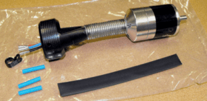
KEEP THE NEW MOTOR FULLY ASSEMBLED!
First remove the OLD motor and mount from your hose:
1. Remove the screws holding the Motor Mount collar on the end of the hose and save the screws and nuts to mount the new motor and mount. One screw also secures the internal stiffener to the interior of the hose. (Some stiffeners are Steel, and some are Fiberglass)
2. Cut the 3 wires for the motor leaving enough cord to crimp (or solder) the wires to the new motor wires. All 3 wires will need to be the same length for this new Motor Connection.
3. You will no longer need any of the parts in the original motor assembly unless you are returning it to Air-Care with an RMA for warranty evaluation.
Installing the NEW Motor Assembly.
1. Be sure you have all the parts for the installation:
- Your original Screws, 10-32 x 5/8” long machine screws,
- 10-32 Hex Nuts with built in Lock Washers.
- Metal or Fiberglass Stiffener (if it was on the original hose)
2. Remove the outer insulation from the black power cord in the hose to expose the 3 insulated motor wires about 2 inches long.
3. Strip the insulation from all 3 wires about ½” back from the ends.
4. Slide the larger black Shrink Tubing over the cable. It will slide over the new connections after the wires are connected.
5. Slide the 3 pieces of smaller shrink tubing over each of the motor wires. The connections can be made by Crimping the new connectors or soldering them. If you are planning to solder the connections, be sure the blue shrink tubing is far enough away from the heated ends to prevent it from shrinking prematurely from the heat of soldering.
6. The wires may be different colors from the Motor than the ones from the hose cable. The order is not important, the brush will operate with any combination of wires, but it may turn in the opposite direction in some cases but will still change directions as before.
7. Each of the 3 wires from the hose can now be inserted into the Crimp connectors on the new motor. Try to twist the wires tight enough so that all the strands go into the silver connector, then crimp it with a crimping tool. Alternately, the wires can be soldered, if so, be sure they are heated to a point where the solder flows into all the strands and into the silver connector. The Motor is a low voltage, HIGH AMP device and a poor connection will result in faulty performance.
8. Slide the Blue shrink tubing over the metal connector; Heat the tubing to shrink it in place. A hair dryer, heat gun or even a cigarette lighter can be used. Be careful to not burn yourself, the plastic hose or heat the other shrink tubing at this time.
9. Connect the other 2 wires following the same procedure.
10. When all 3 wires are connected and insulated, slide the larger black shrink tubing over them and as far towards the motor as possible. Heat this shrink tubing to shrink it on to the wires.
11. Next, slip the Nylon Loop Strap over the wires. This will guide the wires. The Loop Strap will be held in place with one of the 10-32 x 5/8” screws used to hold the black nozzle on the hose.
12. Insert the screws into the mounting holes in the Nozzle and thread the screws into the original holes in the hose if possible. If this is difficult, you may need to drill new holes in the hose using the 2 holes in the Black Nozzle as a guide. Use a 3/16” diameter drill.
13. When the screws are in place, place the loop strap hole over one of the screws and install one of the nuts then tighten the screw with a screwdriver. It may be necessary to use a screwdriver to thread the screws through the loop strap.
14. If your hose has a stiffener, install its loop over the other screw, install the nut and tighten it. If there is no stiffener, just install the nut and tighten the screws.
15. Your repair and upgrade are now complete and ready to test. If you have any questions, please call Air-Care Tech Support, 800-322-9919.
LIMITED WARRANTY
DUCTMASTER III
Air-Care warrants this product to be free from defects in materials and workmanship to the original purchaser for a period of Three (3) years from the date of purchase. Components listed below are excluded from this Three-year period and are covered for periods described below:
Vacuum Motors: 1 Year
Circuit Board & Remote: 1 Year
Power Supply: 1 Year
Hose & Motor Assembly: 90 Days
Brushes, Wheels, & Filter: No Warranty
Warranty covers both parts and labor (labor is to be performed at Air-Care’s facility located at 3868 E. Post Road; Las Vegas, Nevada).
Warranty is extended to the original purchaser and is not transferrable.
This warranty does not extend to any damage to a product caused by or attributable to freight damage, abuse, misuse, improper or abnormal usage. Warranty is also void if the product has been modified or altered in any way.
The purchaser is responsible for the cost of shipping the equipment to Air-Care’s facility for evaluation. If found to be defective and covered by the terms of this warranty, Air-Care will pay FedEx ground shipping charges on the repaired or replaced item back to the purchaser’s location. Any additional expedited service charges for quicker shipping shall be born by the purchaser. If the product or component is not found to be a warranty issue, the purchaser will be responsible for return shipping charges.
Air-Care is not responsible or liable for indirect, special, or consequential damages arising out of or in connection with the use of performance of the product; damages with respect to any economic loss, loss of property, loss of revenues or profits, loss of use, or other incidental or consequential damages of whatsoever nature.
The warranty extended hereunder is in lieu of any and all other warranties, and any implied warranties of any type.
This warranty gives you specific rights. These rights and others vary from state to state.
Division of D.P.L. Enterprises Inc.
3868 East Post Road, Las Vegas, Nevada 89120, (702) 454-5515, FAX (702) 454-5225
Website: www.air-care.com • E-mail: Info@Air-Care.com